Table of Contents
Deployment and Operational Concepts
i3-MARKET architecture specification is based on the 4+1 architectural view model approach. One of these views, Physical View, is the scope of this document. Physical view depicts the system from a system engineer’s point of view. It concerns the topology of software components on the physical layer as well as the physical connections between these components. This view is also known as the deployment view. UML diagrams used to represent the physical view must include the deployment diagram.
Considering this in the i3-MARKET context the Deployment Specification should define execution architecture of systems that represent the assignment (deployment) of software artifacts (i3-MARKET building blocks) to deployment targets (usually nodes).
Nodes represent either hardware devices or software execution environments. They could be connected through communication paths to create network systems of arbitrary complexity. Artifacts represent concrete elements in the physical architecture.
Once the deployment has been provided, a complementary specification would be necessary to define how to deploy software within the i3-MARKET ecosystem. In the context of i3-MARKET we will be referring to this specification as Management Operative specification.
Finally, an end-user operative specification is provided, defining the interaction with i3-MARKET from a stakeholder point of view.
Terminology
The key terms behind I3-MARKET deployment terminology are the following:
Artifact
As it is described in Error: No se encuentra la fuente de referencia, an artifact is a classifier that represents some physical entity, a piece of information that is used or is produced by a software development process, or by deployment and operation of a system. Artifact is a source of a deployment to a node. A particular instance (or “copy”) of an artifact is deployed to a node instance. The most common artifacts are as follows:
- Source files
- Executable files
- Database tables
- Scripts
- DLL files
- User manuals or documentation
- Output files
Artifacts are deployed on the nodes. It can provide physical manifestation for any UML element. Generally, they manifest components. Artifacts are labelled with the stereotype <<artifact>>, and it may have an artifact icon on the top right corner.
Each artifact has a filename in its specification that indicates the physical location of the artifact. An artifact can contain another artifact. It may be dependent on one another.
Artifacts have their properties and behaviour that manipulates them.
Node
As it is introduced in Error: No se encuentra la fuente de referencia, Node is a computational resource upon which artifacts are deployed for execution. A node is a physical thing that can execute one or more artifacts. A node may vary in its size depending upon the size of the project.
Node is an essential UML element that describes the execution of code and the communication between various entities of a system. It is denoted by a 3D box with the node-name written inside of it. Nodes help to convey the hardware which is used to deploy the software.
An association between nodes represents a communication path from which information is exchanged in any direction.
Generally, a node has two stereotypes as follows:
- << device >>: It is a node that represents a physical machine capable of performing computations. A device can be a router or a server PC. It is represented using a node with stereotype <<device>>. In the UML model, you can also nest one or more devices within each other.
- << execution environment >>: It is a node that represents an environment in which software is going to execute. For example, Java applications are executed in java virtual machine (JVM). JVM is considered as an execution environment for Java applications. We can nest an execution environment into a device node. You can net more than one execution environments in a single device node.
The 4+1 View
The 4+1 architectural view model contains the following different views [Source: https://www.cs.ubc.ca/~gregor/teaching/papers/4+1view-architecture.pdf]:
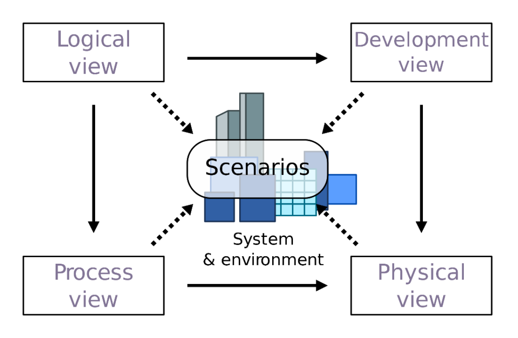
The 4+1 architectural view model was adapted to fit our purposes. To make sure the different interfaces and the communication between our proposed system and the external systems are analysed, the so-called Context View is added to the view model.
The following table describes the different views of the adapted 4+1 architectural view model:
| Architectural view | Description | Diagrams to use |
| Context view | System as a blackbox Interfaces and communication between blackbox and external systems | Context diagrams |
| Logical view | Functionality that the system provides to end-users | Class and state diagrams |
| Process view | Dynamic aspects of the system System processes Runtime behaviour of the system | Sequence, communication and activity diagrams |
| Development/Implementation view | System from a programmer’s perspective Software management | Component diagrams |
| Physical / Deployment view | System from a system engineer’s point of view Topology of software components on the physical layer (and their communication) | Deployment diagrams |
| Scenarios / Use Case view | Sequence of interactions between objects and between processes To identify architectural elements and to illustrate and validate the architecture design Starting point for tests | Use Case Diagrams |
Context View
The context view shows a system as a whole and its interfaces to external factors. System Context Diagrams represent all external entities that may interact with a system, such a diagram pictures the system at the centre, with no details of its interior structure, surrounded by all its interacting systems, environments and activities. The objective of the system context diagram is to focus attention on external factors and events that should be considered in developing a complete set of systems requirements and constraints.
System context diagrams are used early in a project to get agreement on the scope of the system. Context diagrams are typically included in a requirements document. These diagrams must be agreed on by all project stakeholders and thus should be written in plain language, so the stakeholders can understand items within the document.
[Adapted from: Wikipedia [1]]
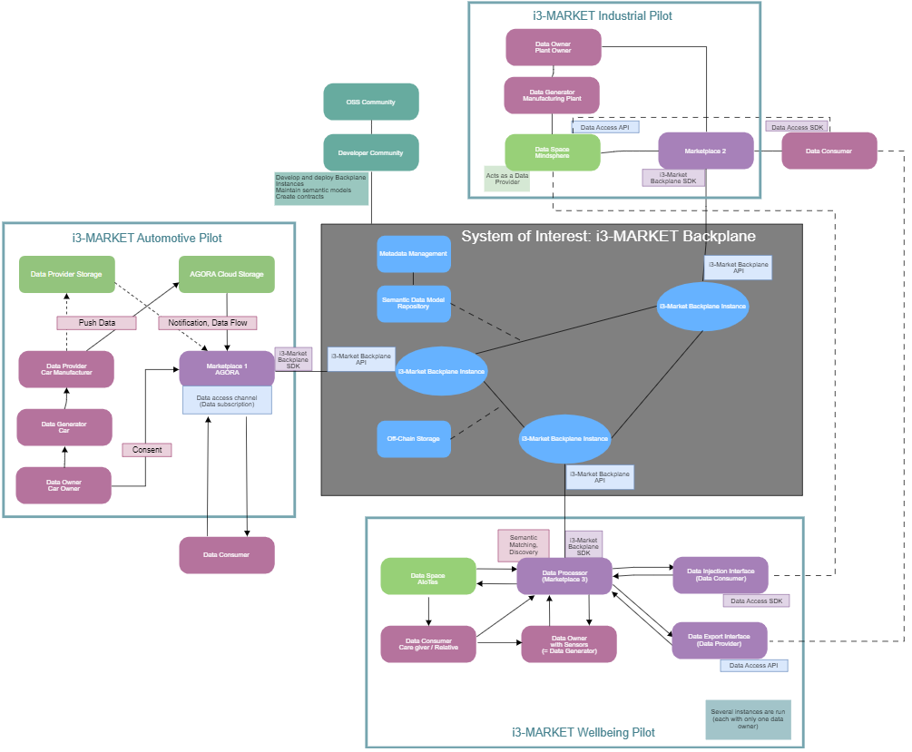
Figure 3 – Context View with i3-MARKET as a blackbox shows the context view of the i3-MARKET backplane. The so-called system of interest, the i3-MARKET backplane is the centre of this diagram, but is considered as a gray-box, showing only little internal details of the system.
The focus of this view are the external actors, that have interfaces to systems. In this case, the external actors are the three pilots of the i3-MARKET project:
- i3-MARKET Automotive Pilot
- i3-MARKET Wellbeing Pilot
- i3-MARKET Industrial Pilot
The figure shows how data consumer and data provider exchange data via the data access API. The Marketplace interacts with the i3-MARKET backplane via an SDK. Both the API and the SDK that will be developed in the project.
The three pilot boxes also show some internal elements of the pilots. Each pilot has their own internal structure, but they share the same interface to the i3-MARKET backplane. This enables seamless data exchange between all marketplaces.
Logical View
The logical view shows the functionality that the system provides to end-users.
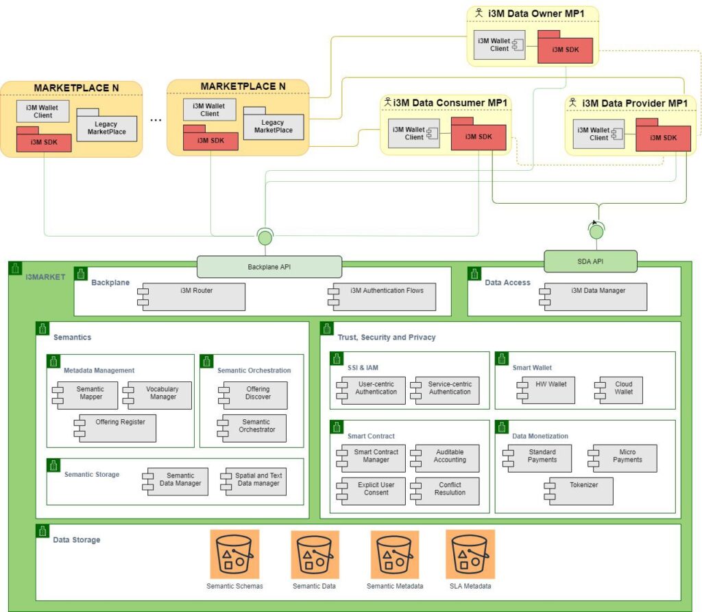
The objective of the logical view is twofold. On one hand, this view shows the i3-MARKET system (green box) and the link between the stakeholders and the marketplaces. On the other hand, the logical view pursues show the internal decomposition of i3-MARKET system into the logical subsystems and components which implement the i3-MARKET backplane API and Secure Data Access API (SDA API).
In general terms, i3-MARKET will support actor with the i3-MARKET Backplane functionality by mean of the two following main entry points:
- The Backplane API and SDA API (depicted as green lines in the picture), or in other words, the direct access to the i3-MARKET Backplane. These two API’s enables access to all integrated building blocks. This is the use case of these actors which follow a more ad-hoc integration with i3-MARKET.
- The i3-MARKET SDK (i3M SDK) (depicted as pink boxes in the picture), to support the end users’ developers with the integration of Backplane API and SDA API. This product is intended for these actors which pursue a more “assisted” support.
Regarding the link with the stakeholder and marketplaces, in the case of the Data Marketplaces actors, i3-MARKET will assist them with fully version of the Backplane API and the i3M SDK (Backplane module) which gives support for interacting with the Backplane API.
In the case of the Data Owner’s, Data Provider’s and Data Consumer’s, the normal operating mode will be the access to i3-MARKET Backplane through their own data marketplace. However, for some particular data marketplaces cases, Data Owner’s, Data Provider’s and Data Consumer’s, will have the possibility to directly interface with i3-MARKET system through the available SDK’s and API’s. More specifically, i3-MARKET will allow direct communication with the stakeholder by means of following components:
- Data Owner, through the i3M SDK (Backplane module) which gives support for interacting with the Backplane API (light green lines in the picture).
- Data Provider, thorough the i3M SDK-Backplane module which gives support for interacting with the Backplane API (light green lines in the picture) and the i3M SDK-Secure Data Access API which gives support for interacting with the Secure Data Access API (dark green lines in the picture).
- Data Consumer, through the i3M SDK-Backplane module which gives support for interacting with the Backplane API and the i3M SDK-Secure Data Access API which gives support for interacting with the Secure Data Access API.
In order to guarantee the authentication mechanisms proposed by i3-MARKET, a Wallet Client should be installed into the end user side in order to store the user private keys.
At the closure of this document, it remains open whether i3-MARKET will allow direct connection between Data Owner-Data Provider (for consent facets) and Data Consumer-Data Provider (for data transfer facets) or otherwise these interactions will always take place via the data marketplaces.
Regarding the internal breakdown of i3-MARKET system, five big subsystems are represented:
- The Backplane API gives access to all i3-MARKET functionality. In particular:
- Semantic Building Block, in charge of providing all the components related with semantic data model, semantic metadata and semantic repositories.
- Trust, Security and Privacy Building Block, in charge of assisting the end user with all the authentication and authorization aspects of the i3-MARKET. Also P2P interaction between stakeholder provided by Smart Contract manager and Data monetization.
- Data Storage Building Block, in charge of providing the distributed and decentralized storages in i3-MARKET.
- The SDA API, by mean of which the data consumer gain access to the data offered by the data provider
Each of these subsystems are fully detailed in section Development View.
Process View
According to [2] the process view “takes into account some non-functional requirements, such as performance and availability. It addresses issues of concurrency and distribution, of system’s integrity, of fault-tolerance, and how the main abstractions from the logical view fit within the process architecture—on which thread of control is an operation for an object actually executed”.
Following this approach, the i3-MARKET process view should show the interaction between the process and threads of the system representing, among others non-functional characteristics, concurrency, synchronisation, availability, or performance.
From a diagram point of view, Booch stated “… the static and dynamic aspects of this view are captured in the same kinds of diagrams as for the design view – i.e. class diagrams, interaction diagrams, activity diagrams and statechart diagrams, but with a focus on the active classes that represent these threads and processes.” [6]
A fine-grained detail is demanded for identifying the actives objects (process and threads), which are instances of actives classes, and the way they communicate between each other (synchronous/asynchronous) which is needed for this view. Due to that, the i3-MARKET process view definition will be accomplished between the different technical tasks (T3.1-T4.3). These tasks provide more specification details, on the way to the class and message-level needed for this process view, than the current architecture deliverable, which is more focused on high-level i3-Market system and subsystems overview.
Development View
According to [2] the development view “focuses on the actual software module organization…The software is packaged in small chunks—program libraries, or subsystems—that can be developed by one or a small number of developers. The subsystems are organized in a hierarchy of layers, each layer providing a narrow and well-defined interface to the layers above it”
Therefore, the objective of the development view is twofold:
- Giving a system view from a programmer’s perspective which might help in the development process.
- Support the software management by monitoring the accomplishing of subsystem and component depicted in the diagrams.
For the process of defining the development view, i3-MARKET has followed the guidelines proposed by arc42 template [7] for architecture construction and documentation, which is summarized in the following section.
Approach
The i3-MARKET “Development view” is documented following the “Building Block view” from arc42 template. Following are cited the instructions provided by the template:
Content
The building block view shows the static decomposition of the system into building blocks (modules, components, subsystems, classes, interfaces, packages, libraries, frameworks, layers, partitions, tiers, functions, macros, operations, data structures, …) as well as their dependencies (relationships, associations, …).
This view is mandatory for every architecture documentation. In analogy to a house this is the floor plan.
Motivation
Maintain an overview of your source code by making its structure understandable through abstraction. This allows you to communicate with your stakeholder on an abstract level without disclosing implementation details.
Form
The building block view is a hierarchical collection of black boxes and white boxes (see figure below) and their descriptions.
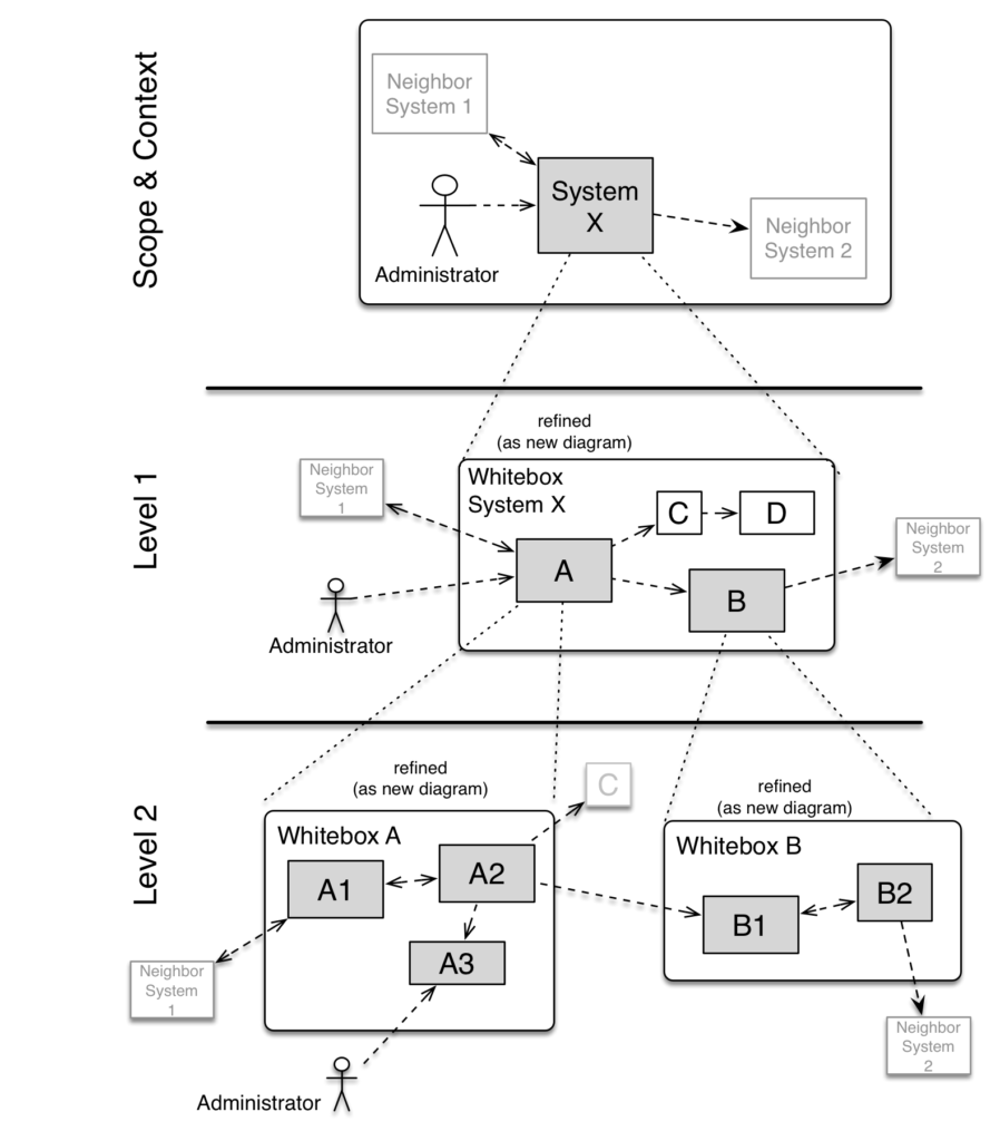
Level 1 is the white box description of the overall system together with black box descriptions of all contained building blocks.
Level 2 zooms into some building blocks of level 1. Thus it contains the white box description of selected building blocks of level 1, together with black box descriptions of their internal building blocks.
Level 3 zooms into selected building blocks of level 2, and so on.”
In i3-MARKET will follow the following arc42-based template for the documentation of the Level 1 development view.Here you describe the decomposition of the overall system using the following white box template. It contains
- an overview diagram
- a motivation for the decomposition
- black box descriptions of the contained building blocks (use a list of black box descriptions of the building blocks according to the black box template (see below). Depending on your choice of tool this list could be sub-chapters (in text files), sub-pages (in a Wiki) or nested elements (in a modelling tool).”
Do you want to read more about the i3-MARKET Architecture?
Deployment View
According to [2] the deployment or physical view “describes the mapping(s) of the software onto the hardware and reflects its distributed aspect”.
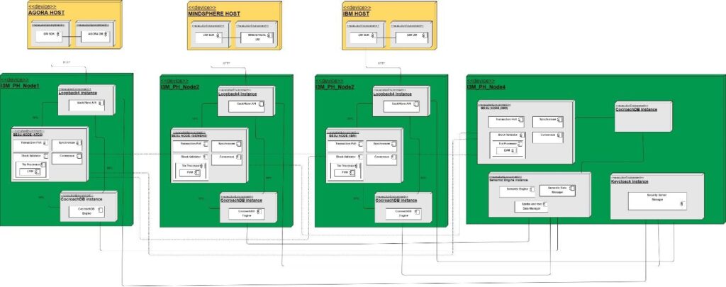
Following this approach, the i3-MARKET deployment view is depicted in the picture below. Four nodes constituted the i3-MARKET R1 cluster. On each node it will be deployed a Backplane Gateway System and an instance of all the rest i3-MARKET main building blocks (Trust, Security and Privacy System, Storage System, and Data Access System) giving backend support to the Backplane Gateway System. In addition to that, node 4 will host all the components related with the Semantic Engine Building Block.
To realize the blockchain-based feature which gives support to the i3-MARKET component, a blockchain network based on Hyperledger Besu [https://www.hyperledger.org/use/besu] will be deployed.
References
[1] https://en.wikipedia.org/wiki/System_context_diagram
[2] P. Kruchten, “Architectural Blueprints — The “4+1” View Model of Software Architecture,” IEEE Software 12, November 1995, pp. 42-50.
[3] J. R. a. I. J. G. Booch, UML User Guide, Addison-Wesley Longman, 1998.
Free* Open Source Software Tools for SMEs, Developers and Large Industries Building/Enhancing their Data Marketplaces.
For more detail and source code please refer below link.
Go to the beginning of the page
Other resources of interest
Home
We are a community of experienced developers who understand that it is all about changing the perception of data economy via marketplaces support.
Data Access API
The secure Data Access API enables data providers secure registration…
Data Storage
The Decentralised storage shall provide highest available security guarantees…
Identity and Access Management
The SSI & IAM subsystem is in charge of providing both “User-centric Authentication” and…
Smart Contracts, Wallets & Accounting
i3-M Wallet is a set of technologies that facilitate the management of their identity to…
Crypto Token and Monetization System
The Data Monetization subsystem is in charge of providing “Standard Payments”…
Semantic Engine
We developed and implemented dedicated software components for Semantic Engine System as…
Specification Deployment
i3-MARKET architecture specification is based on the 4+1 architectural view model approach. One of…
Developers Quickstart SDK
Once a marketplace is part of i3-MARKET, it can issue credentials to its consumers, providers, and…